
The use of reverse engineering equipment for dimensional and geometric control is becoming increasingly common, as their versatility and precision make them a viable option compared to higher-precision equipment such as Coordinate Measuring Machines (CMMs) in certain fields.
Just as there is a wide variety of calibration patterns for CMMs, the same is not true for reverse engineering equipment. Nowadays, reverse engineering equipment is capable of obtaining measurements with accuracies that approach those of a CMM. Therefore, a research study was conducted by the Department of Manufacturing Processes Engineering at the Polytechnic School of Gijón in collaboration with Dogram, in which a pattern of characteristics was designed and fabricated for the calibration of reverse engineering equipment.
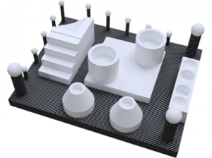
Fig.1. Ceramic Pattern
A ceramic pattern was designed and fabricated, as shown in Fig. 1, upon which a comprehensive dimensional and geometric control can be conducted. Fig. 2 illustrates the different parts or entities composing the ceramic pattern.
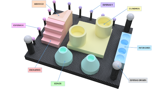
Fig.2. Different parts composing the Ceramic Pattern.
The following parameters are evaluated on these different entities of the pattern:
- Distance in space between sphere centers, cylinder axes, and planes.
- Diameters of spheres and cylinders.
- Form error of spheres, planes, cylinders, and cones.
- Angle of inclination of planes and cones.
- Parallelism between cylinders, cones, and planes.
- Perpendicularity between planes.
- Coaxiality between cylinders.
Once the parameters to be evaluated on the pattern are established, measurements are taken using the different available equipment.
The first equipment used for measuring the pattern was the Coordinate Measuring Machine (CMM), in order to obtain reference values.
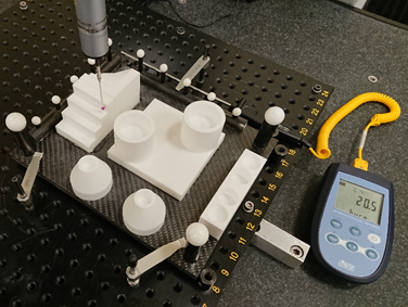
Fig.3. Measurement by contact of the Ceramic Pattern on the Coordinate Measuring Machine (CMM).
Next, the measurement was performed using the non-contact measurement equipment available at Dogram. The equipment used was the RS6 triangulation laser sensor from Hexagon Metrology mounted on the Absolute Arm 8525-7 Coordinate Measuring Arm.
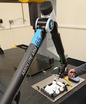
Fig.4. Measurement with the RS6 laser sensor mounted on the Absolute Arm 8525-7 Coordinate Measuring Arm.
The scanning of the ceramic pattern with the RS6 equipment ultimately results in obtaining a point cloud, which will be processed later to evaluate the study parameters upon it.
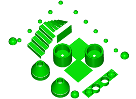
Fig.5. Point cloud belonging to the RS6 laser sensor after removing points not belonging to the evaluated entities.
Based on the study of the point cloud, a results report is obtained to conduct a comparative study between both equipment. The following graphs depict the deviations of the values obtained with the RS6 triangulation laser sensor compared to the values obtained in the CMM for the different parameters evaluated according to the type of entity. The y-axis represents the deviation expressed in millimeters, while the x-axis shows the type of entity.
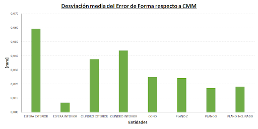
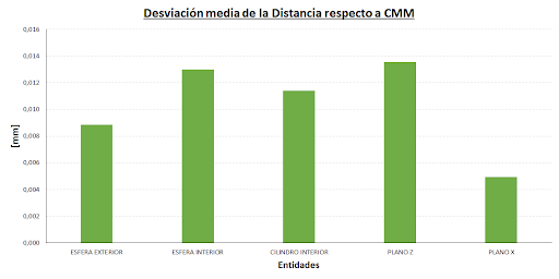
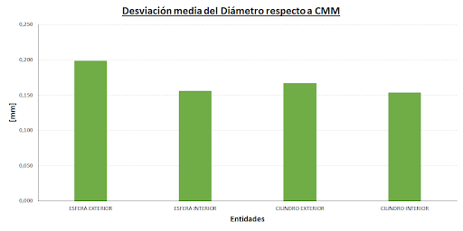
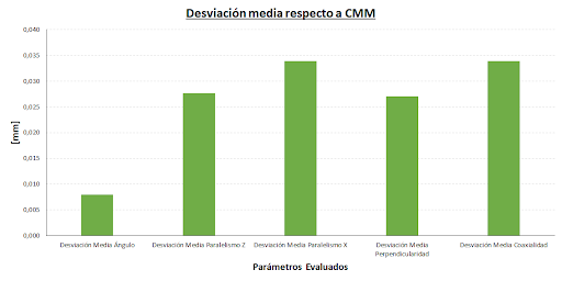
As can be observed from the obtained graphs, the deviations for the RS6 laser deviate by approximately 0.050 millimeters from the reference value obtained by the CMM. This means that for applications that do not require tolerances close to 0.001 millimeters, the use of the RS6 triangulation laser sensor from Hexagon Metrology mounted on the Absolute Arm 8525-7 Coordinate Measuring Arm is highly recommended.
The significant advantage of such equipment over a CMM is its versatility and speed of measurement, as well as the cost factor. As demonstrated in the conducted study, if the application for the RS6 equipment does not require tolerances close to the micrometer range, its use is recommended over that of the CMM.